Support Definition
This window is used to define supports. The left pane displays a list of supports available in the model, while the right pane shows the properties of the selected support. The same area is also used to input parameters when creating a new support.
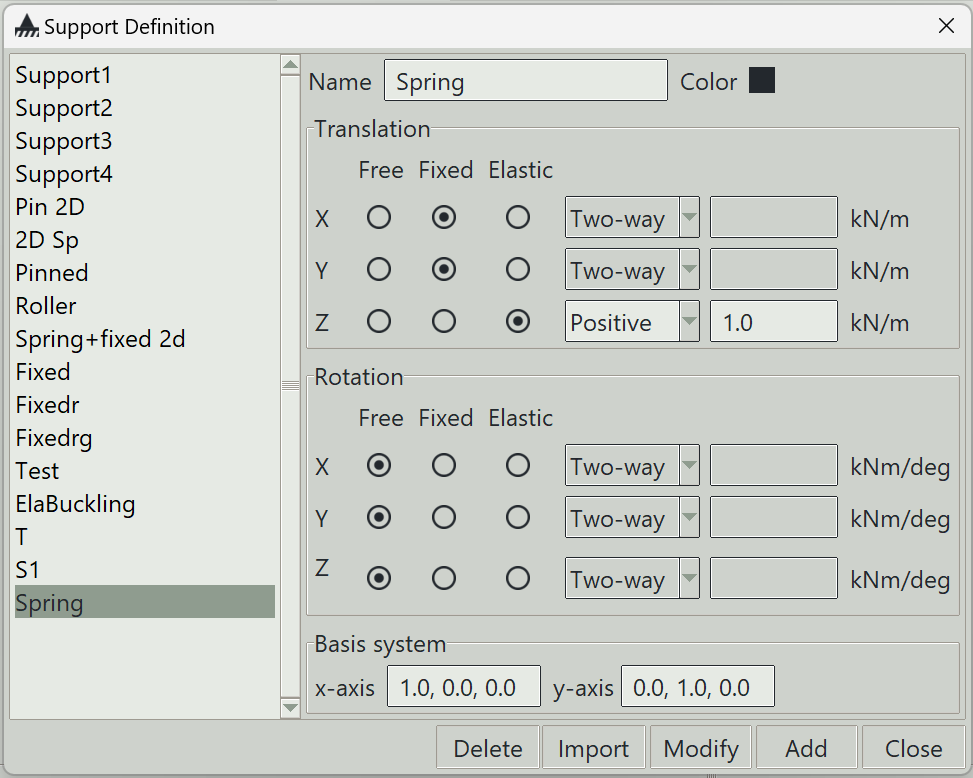
1. Name
A unique name for the support. It can be left blank, in which case the program will generate one automatically.
2. Color
The color assigned to this support for visualisation purposes.
3. Translation
In this section, you can specify support conditions for translation in the local x, y, and z directions. There are three general types of support conditions:
- Free: The degree of freedom is allowed to translate freely.
- Fixed: The degree of freedom is restrained from any translation.
-
Elastic: The degree of freedom is allowed to translate by an amount proportional to the applied force. A stiffness value (spring constant) must be specified. Additionally, you must define whether the spring resists:
- Both positive and negative translation (Two-way)
- Only positive translation (Positive)
- Only negative translation (Negative)
4. Rotation
In this section, you can specify support conditions for rotation about the local x, y, and z axes. There are three general types of support conditions:
- Free: The degree of freedom is allowed to rotate freely.
- Fixed: The degree of freedom is restrained from any rotation.
- Elastic: The degree of freedom is allowed to rotate by an amount proportional to the applied moment. A stiffness value (rotational spring constant) must be specified. Additionally, you must define whether the spring resists:
- Both positive and negative rotation (Two-way)
- Only positive rotation (Positive)
- Only negative rotation (Negative)
5. Basis system
Supports are defined in the global coordinate system by default. However, they can also be defined in a local coordinate system. This is especially useful when defining inclined roller supports.
5.1 x-axis
The i, j, k components of a non-zero vector defining the local x-axis of the support.
5.2 y-axis
The i, j, k components of a non-zero vector defining the local y-axis of the support.
The local z-axis is automatically calculated from the x-axis and y-axis following the right-hand rule.
6. Delete button
Removes the selected supports from the model.
7. Import button
Opens a window that allows you to import predefined supports.
8. Modify button
Updates the properties of the selected support.
9. Add button
Creates a new support using the specified parameters.
10. Close button
Closes the window.