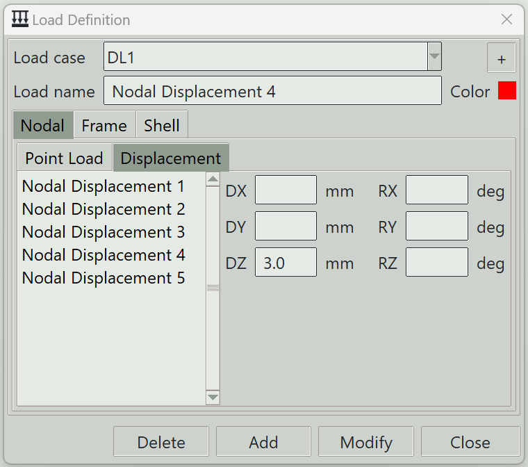
Nodal Displacement Definition
This tab is used to define nodal displacements, which are treated as a type of load. The left pane displays a list of nodal displacements available in the model, while the right pane shows the parameters of the selected displacement. The same area is also used to input parameters when creating a new nodal displacement.
This feature is the primary way of assessing the effects of support settlement. When a displacement is applied to a degree of freedom, any existing support condition assigned to that degree of freedom is overridden, as the imposed displacement takes precedence. In theory, applying a fixed support is equivalent to enforcing zero displacement. Hence you can apply fixed supports using this method, with the added advantage that it can be defined per load case, whereas standard support assignments apply to all load cases.
1. Load case
Select the load case under which this displacement is defined.
2. + button
Opens the load case definition window so that you can add a new load case.
3. Load name
A unique name for the load. It can be left blank, in which case the program will generate one automatically.
4. Color
The color assigned to this displacement for visualisation purposes.
5. Load components
A set of entry fields is provided where you can define the components of the displacement vector. At least one component must be specified for the definition to be valid. A zero value means the corresponding degree of freedom will experience zero displacement, similar to a fixed support condition.
- DX: Displacement in the local x-axis of the node.
- DY: Displacement in the local y-axis of the node.
- DZ: Displacement in the local z-axis of the node.
- RX: Rotation about the local x-axis of the node.
- RY: Rotation about the local y-axis of the node.
- RZ: Rotation about the local z-axis of the node.
Yes, nodes can have local axes too. For Songeya, when you assign a rotated support to a node, you essentially rotate the node. To simplify mathematical formulation, Songeya applies the prescribed displacements in this rotated system. However, the other type of nodal loads are still applied in the global coordinate system.
6. Delete button
Removes the selected displacement from the model.
7. Add button
Creates a new displacement using the specified parameters.
8. Modify button
Updates the parameters of the selected displacement.
9. Close button
Closes the window.