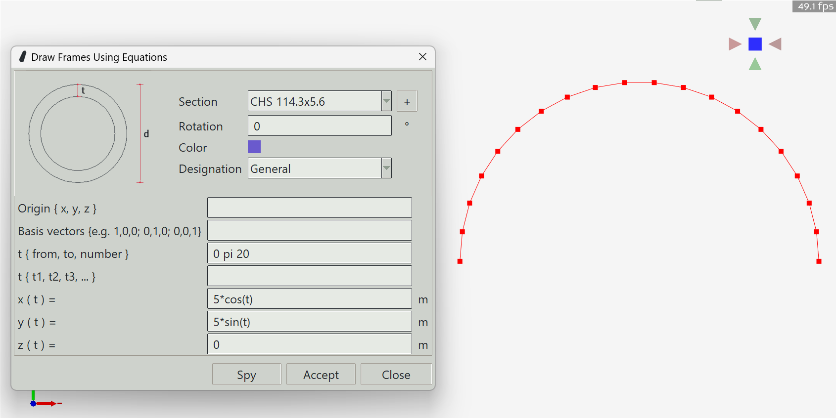
Draw Frame Using Equations
Songeya provides a method to draw frames using parametric equations. This way, you can draw any imaginable structural geometry. As long as you know the equations that define the shape you want, you can draw it very easily. To use this feature, you define a range of values for the parameter t, then define the expressions for x, y, and z. You can use the spy button to preview what you are trying to create and press the Accept button when you are satisfied. The expressions for x, y, and z must be mathematically valid. Common math symbols are supported.
Note that this does not generate a single frame. Rather, it generates a series of connected frames that form the geometric shape you want. In Songeya, there is no such thing as a curved frame.
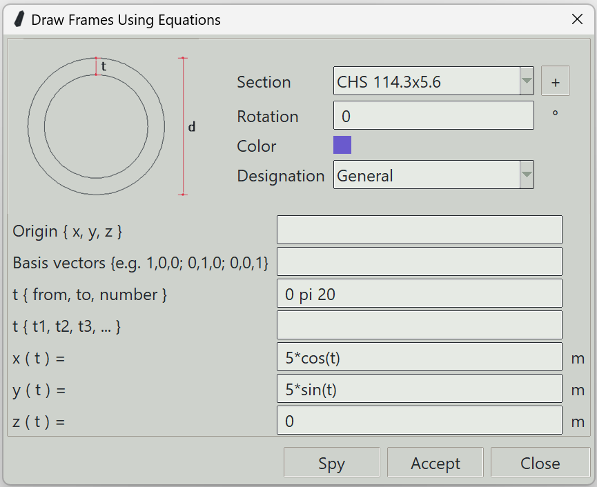
1. Section
The name of the section to assign to the frames.
2. + button
Opens the section definition window so that you can define a new section.
3. Rotation
Songeya will automatically decide an initial orientation of the frame. By default, it will try to make the local z-axis of the frame point upwards. You can specify a rotation here so that the local z-axis points wherever you want.
4. Color
The color assigned to the frames for visualisation.
5. Designation
Specifies whether the frames are beams, columns, or truss members. If you select truss, the program will automatically add releases. You can find out more about releases here. It is also here that you can define whether the bars are tension-only or compression-only members.
6. Origin
When you specify expressions for the spatial coordinates, you can optionally specify the basis system in which those expressions are defined. This can be useful when you want to place the geometry at some location in space, but the expressions you have are better expressed from (0,0,0). You can set a basis system by specifying a different origin and three basis vectors. In this entry box, you can specify the origin. If you leave it blank, the program will assume 0,0,0.
7. Basis vectors
Here, you specify three vectors that define the coordinate system. If you leave it blank, the program will assume 1, 0, 0; 0, 1, 0; 0,0,1.
8. t { from, to, number }
The parametric variable t can be given a range of values by specifying a starting value, the ending value, and the number of values.
9. t { t1, t2, t3, ... }
You can also enter a list of t values manually. This entry and the one above will be combined to form one unified range of values for t.
10. x ( t )
A mathematically valid expression for the x coordinate in terms of t. Common math symbols are supported.
11. y ( t )
A mathematically valid expression for the y coordinate in terms of t. Common math symbols are supported.
12. z ( t )
A mathematically valid expression for the z coordinate in terms of t. Common math symbols are supported.
13. Spy button
Previews the entered parameters by drawing a sketch of the described geometry in 3D space.
14. Accept button
Adds a series of frames as described by the parametric equations.
15. Close button
Closes the window and ends the frame drawing command.