Grid Definition
The Grid Definition dialog is used to create, modify, and manage grids in the model. The left panel displays the names of the grids available in the model, while the right panel shows the properties of the selected grid.
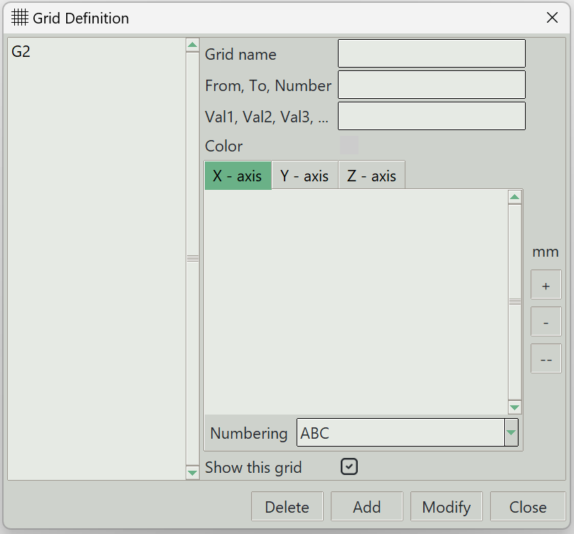
1. Grid name
A unique name for the grid system. It can be left empty, and the program will generate one automatically.
2. From, To, Number
Defines the grid values using a start value, end value, and the number of grid values.
3. Val1, Val2, Val3
Allows manual entry of specific grid values.
4. Color
Displays or selects the grid line color.
5. X-Axis, Y-Axis, and Z-Axis tabs
Switch tabs to set the active axis. The entered grid values will be assigned to this axis, and any existing grid values for the selected axis are displayed.
6. + button
Adds grid values. When clicked, the values entered are assigned to the active axis.
7. - button
Removes selected grid values from the active axis.
8. -- button
Removes all grid values from the active axis.
9. Numbering
Selects the numbering style for grid labels.
10. Show this grid
Determines whether this grid is visible in the model.
11. Delete button
Removes the selected grid from the model.
12. Add button
Adds a new grid to the model.
13. Modify button
Applies changes to the selected grid.
14. Close button
Closes the dialog.