Draw Shell Using Equations
Songeya provides a method to draw shells using parametric equations. This allows you to create almost any imaginable structural geometry. As long as you know the equations that define the shape you want, you can generate it easily.
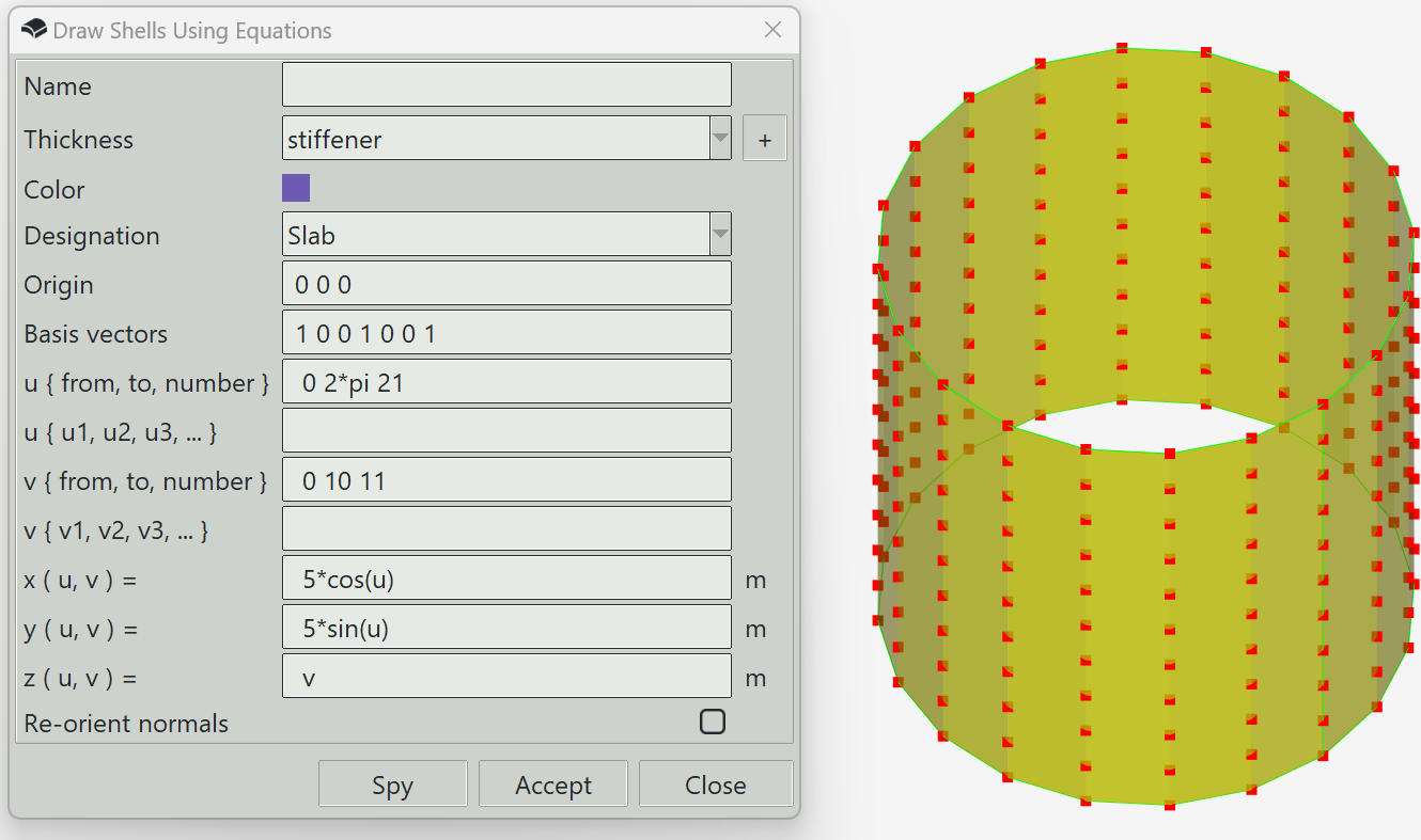
To use this feature, define a range of values for two parameters, u and v, and then specify expressions for x, y, and z. You can use the Spy button to preview the geometry and click the Accept button when you are satisfied. The expressions for x, y, and z must be mathematically valid. Common mathematical functions and symbols are supported.
Note that this feature does not generate a single shell. Instead, it creates a collection of connected shells that approximate the desired geometry. In Songeya, curved shells are not supported directly. The generated shells can be subdivided later to achieve the required mesh size during analysis. Alternatively, you can define a finer mesh here to avoid further subdivision, which generally results in better mesh quality. However, this will require more computational resources since the model will contain many small shells.
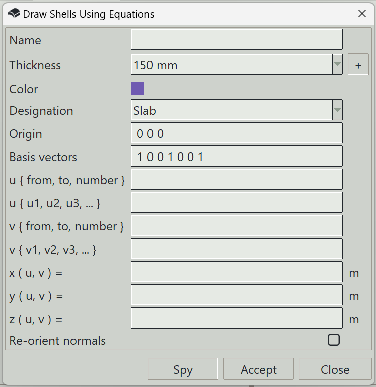
1. Name
You can optionally specify a name for the shell. Otherwise, the program will generate one automatically.
2. Thickness
The thickness property to assign to the generated shells.
3. + button (thickness)
Opens the thickness definition window so that you can define a new thickness.
4. Color
The color assigned to the shells for visualization.
5. Designation
Specifies whether the shells represent walls or slabs. This information can be useful during design, if supported by your design script.
6. Origin
You can optionally specify the coordinate system in which the equations are defined. This is done by defining an origin and three basis vectors. In this field, you can specify the origin. If left blank, the program assumes 0, 0,0.
7. Basis vectors
Here, you specify three vectors that define the coordinate system. If left blank, the program assumes 1,0,0,0,1,0,0,0,1.
8. u { from, to, number }
The parametric variable u can be defined over a range by specifying a starting value, an ending value, and the number of divisions.
9. u { u1, u2, u3, ... }
You can also enter a list of u values manually. This entry and the one above are combined to form a unified set of values for u.
10. v { from, to, number }
The parametric variable v can be defined over a range by specifying a starting value, an ending value, and the number of divisions.
11. v { v1, v2, v3, ... }
You can also enter a list of v values manually. This entry and the one above are combined to form a unified set of values for v.
12. x (u, v)
A mathematically valid expression for the x coordinate in terms of u and v. Common mathematical functions are supported.
13. y (u, v)
A mathematically valid expression for the y coordinate in terms of u and v. Common mathematical functions are supported.
14. z (u, v)
A mathematically valid expression for the z coordinate in terms of u and v. Common mathematical functions are supported.
15. Re-orient normals
When this option is enabled, the program adjusts the local z-axis of each shell so that it points as close to upward as possible. If disabled, the original (raw) z-axis directions are preserved. This can be preferable in certain cases. For example, when defining a sphere, you may want all normals to point consistently inward or outward, rather than being adjusted to point upward.
16. Spy button
Previews the entered parameters by drawing a sketch of the geometry in 3D space.
17. Accept button
Creates shells as defined by the parametric equations.
18. Close button
Closes the window and ends the shell drawing command.