Buckling
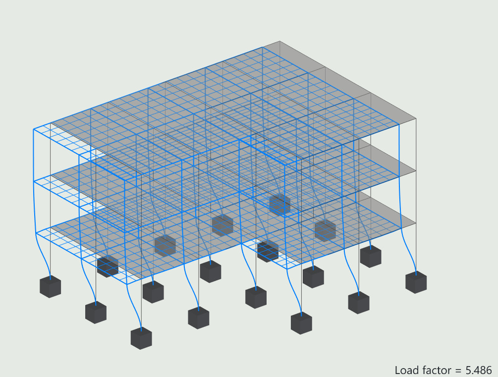
This tab is used to visualise the buckling modes of the model. If you have performed a buckling analysis, these are the only results available for exploration. You can display the total mode shape, or the mode shape in each of the three global directions.
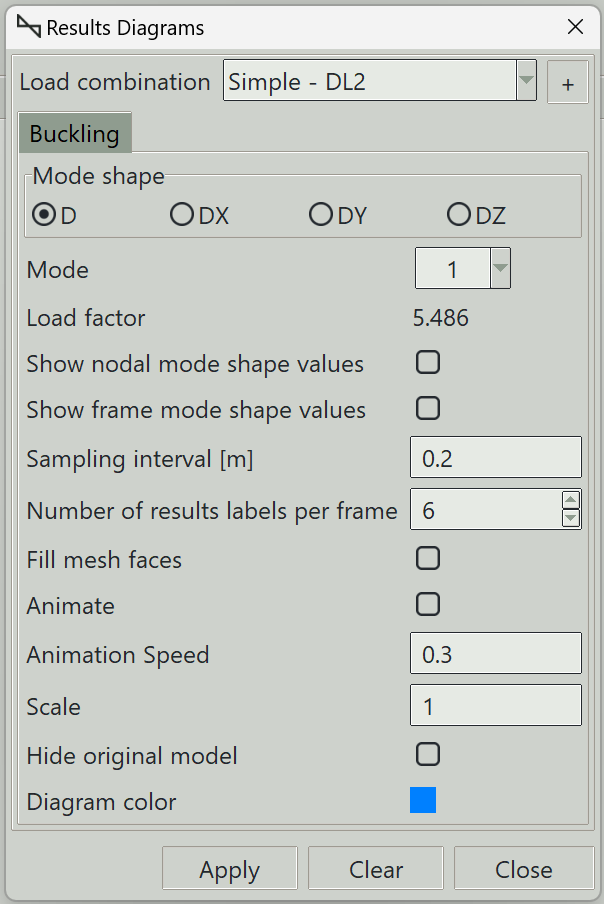
1. Load combination
The name of the load combination to display results for.
2. Mode shape
You can visualise the total mode shape, or the mode shape in each of the three global directions:
- D: Total mode shape.
- DX: Mode shape in the global x-direction
- DY: Mode shape in the global y-direction
- DZ: Mode shape in the global z-direction
3. Mode
The buckling mode to visualise results for.
4. Show nodal displacement values
Whether to display mode shape values at nodes.
5. Show frame displacement values
Whether to display mode shape values along frame elements.
6. Sampling interval
Defines the spacing of sampling points along frames where mode shape values are evaluated. Smaller values produce smoother results.
7. Number of results labels per frame
Specifies how many result labels are displayed along each frame.
7.1 Filled mesh faces
Controls whether deformed shell elements are displayed as filled surfaces or wireframe.
8. Animate
Enables animation of the mode shape.
8.1 Animation speed
Controls the speed of the animation. Higher values produce faster motion.
9. Scale
Controls the amplification factor of the displayed mode shape.
10. Reset button
Use this button to reset the scale.
11. Hide original model
Hides the original model when displaying the mode shape.
12. Diagram color
Sets the color used to display the mode shape.
13. Apply button
Displays the mode shape in the specified direction. If some elements are selected, results are displayed only for those elements.
14. Clear button
Clears all result graphics from the model view.
15. Close button
Closes the window and clears all result graphics.