Draw Reinforcement
Songeya allows you to define reinforcement layouts within concrete sections of arbitrary shape. You can place reinforcement freely anywhere within the section. Depending on your chosen design approach, this functionality can be highly useful. You may define reinforcement layouts and then develop custom design scripts to verify the adequacy of the reinforcement for bending, shear, and serviceability limit states. With the aid of powerful geometry libraries such as Shapely, it is relatively straightforward for you to implement scripts for calculating bending capacity, even for sections with complex shapes and arbitrary reinforcement arrangements. This remains manageable even when considering biaxial bending. Songeya includes bending capacity scripts based on Eurocode 2, which you can adapt to suit other design standards. Shear and deflection checks, however, are generally more challenging for you to automate for arbitrary section geometries, as robust analytical models are limited. These checks are typically reliable only for well-known section types. For unconventional shapes, you will need to simplify them through conservative assumptions.
This window provides a drawing area where you can interactively place reinforcement bars. Bar positions may also be specified numerically using the input fields on the right. You can select, delete, move, and edit reinforcement bars individually or as groups.
The top ribbon includes three primary tools:
- Add (+): Activates drawing mode for placing reinforcement bars.
- Select: Enables selection mode for modifying existing bars.
- Delete: Removes selected reinforcement bars.
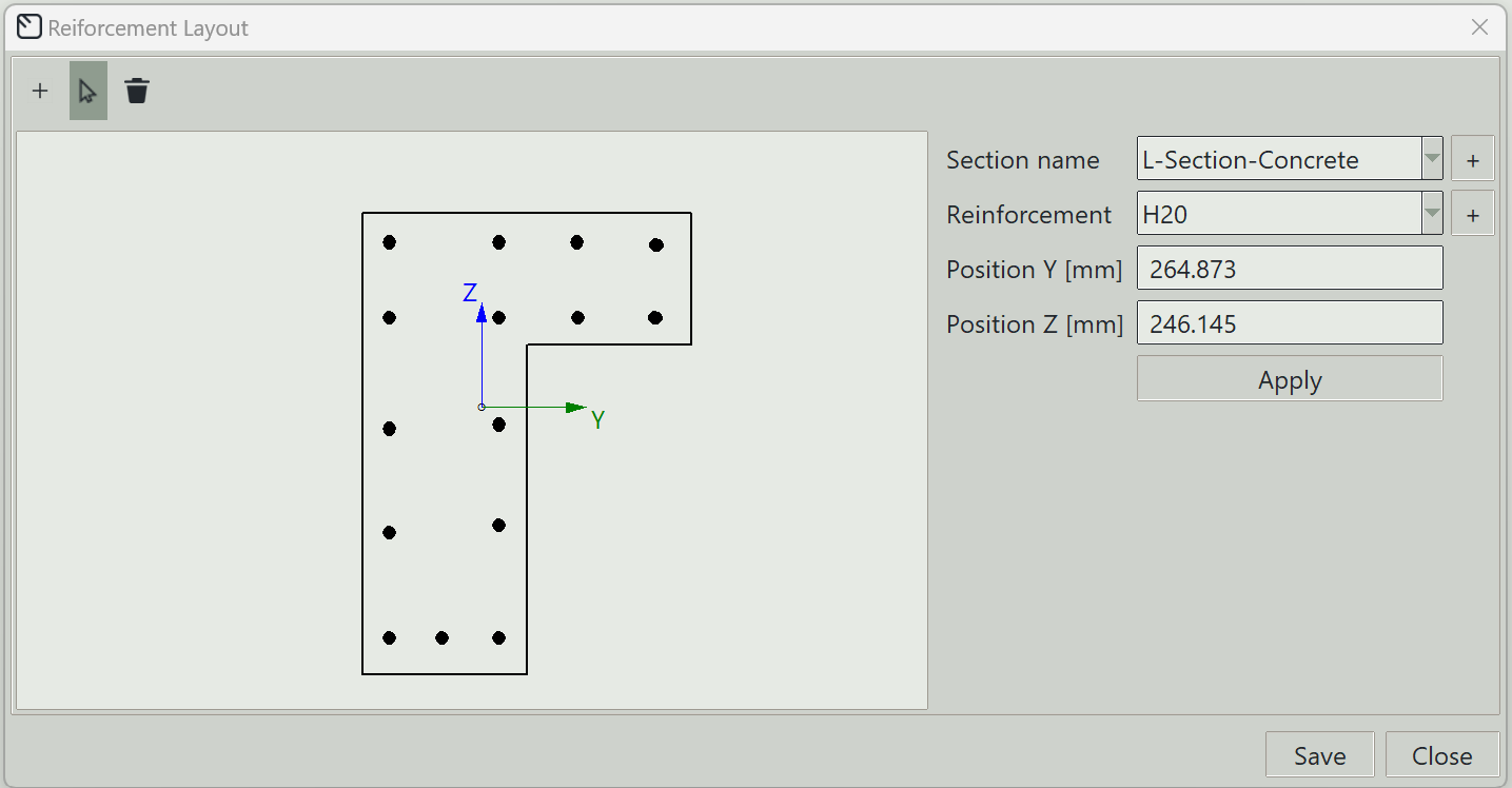
1. Section name
Select the concrete section on which you want to draw the reinforcement layout.
2. Reinforcement
Select the reinforcement bar you want to add to the section.
3. Add button (+)
Opens the reinforcement definition window so you can define new reinforcement.
4. Position Y
The y-coordinate of the reinforcement bar in the local axis of the section. The origin of the section coordinate system is at the centroid.
5. Position Z
The z-coordinate of the reinforcement bar in the local axis of the section. The origin of the section coordinate system is at the centroid.
6. Apply button
Applies the entered properties to any selected reinforcement bars in the section. If none are selected, a new reinforcement bar is drawn.
7. Save button
Saves the reinforcement layout for the section.
8. Close button
Closes the window.