Frames
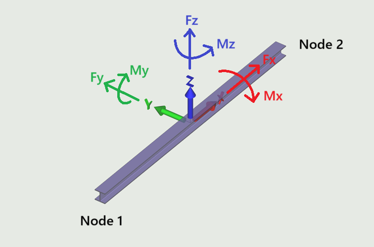
This tab is used to visualise the internal forces in frames. The sign convention is the usual right hand system as shown.
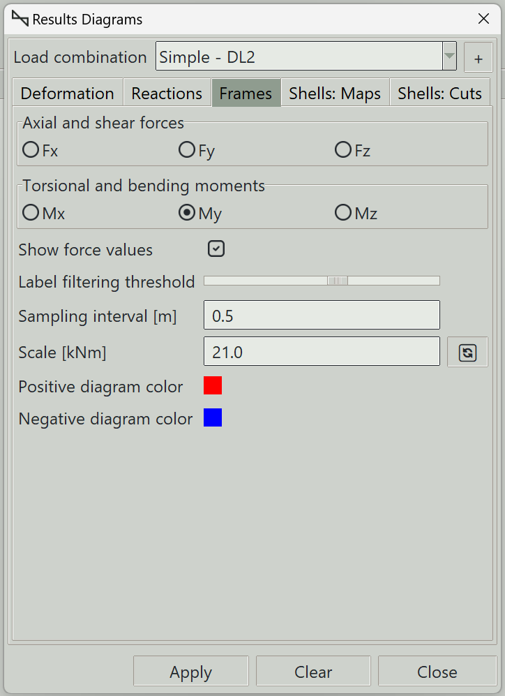
1. Load combination
The name of the load combination to display results for.
2. Axial and shear forces
You can select the type of force diagram to visualise:
- Fx: Axial force. Compression is positive and tension is negative.
- Fy: Shear force in the local y-axis.
- Fz: Shear force in the local z-axis.
3. Torsional and bending moments
You can select the type of moment results to extract:
- Mx: Torsional moment (moment around the local x-axis).
- My: Bending moment about the local y-axis.
- Mz: Bending moment about the local z-axis.
4. Show force values
Whether to display results values along frame elements.
5. Label filtering threshold
A slider that controls the tolerance for selecting which points along the result diagram are labeled. Higher values increase the selection tolerance, resulting in fewer labeled points. Lower values reduce the tolerance and display more labels.
6. Sampling interval
Defines the spacing of sampling points along frames where results are evaluated. Smaller values produce smoother results.
7. Scale
Controls the sizes of the diagrams. The smaller the number the larger the results diagram.
8. Positive diagram color
Sets the color used to display the positive sides of diagrams.
9. Negative diagram color
Sets the color used to display the negative sides of diagrams.
10. Apply button
Displays the selected frame results. If some elements are selected, results are displayed only for those elements.
11. Clear button
Clears all result graphics from the model view.
12. Close button
Closes the window and clears all result graphics.