Shell Distributed Edge Load Definition
This tab is used to define distributed loads that can be assigned to shells' edges. The left pane displays a list of shell edge loads available in the model, while the right pane shows the parameters of the selected load. The same area is also used to input parameters when creating a new shell edge load.
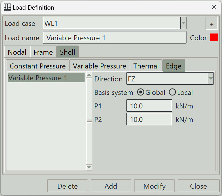
1. Load case
Select the load case under which this load is defined.
2. + button
Opens the load case definition window so that you can add a new load case.
3. Load name
A unique name for the load. It can be left blank, in which case the program will generate one automatically.
4. Color
The color assigned to this load for visualisation purposes.
5. Direction
Specifies the direction of the distributed load:
- FX: Force component in the global or local x-axis.
- FY: Force component in the global or local y-axis.
- FZ: Force component in the global or local z-axis.
- MX: Moment force component about the global or local x-axis.
- MY: Moment force component about the global or local y-axis.
- MZ: Moment force component about the global or local z-axis.
6. Basis system
You can define the load in either the global coordinate system or the shells’s local coordinate system.
7. P1
The intensity of the distributed load at the first end of the edge.
8. P2
The intensity of the distributed load at the other end of the edge.
9. Delete button
Removes the selected load from the model.
10. Add button
Creates a new load using the specified parameters.
11. Modify button
Updates the parameters of the selected load.
12. Close button
Closes the window.