Bracing Definition
The location of restraints is required in steel and concrete frame design. These locations are the starting point for defining effective lengths. This window gives the ability to define these restraint locations, which can later be assigned to frames. This is only useful if your design script supports it. Songeya does not use this anywhere else. It is only through the API that the locations defined through this method are exposed. So you can write your design script to pull restraint locations and be able to define effective lengths. The left pane of the window shows a list of available bracing properties in the model. The right side displays the parameters of the selected bracing property. This is also where the parameters for a new bracing property are entered.
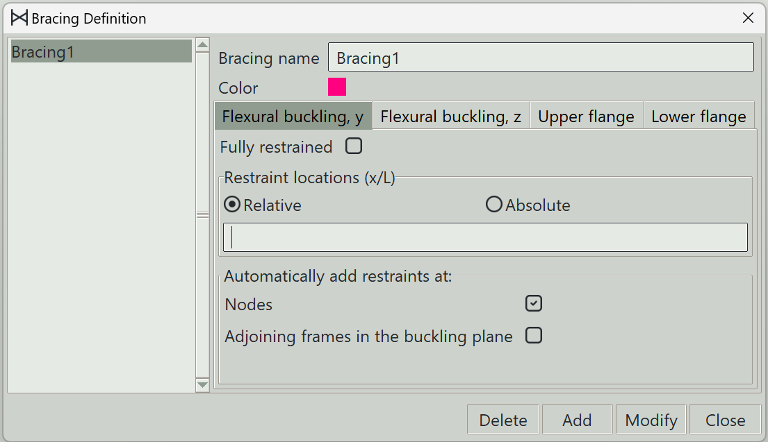
1. Bracing name
A unique name for the bracing. It can be left empty, and the program will generate one automatically.
2. Color
A color to give to this bracing for visualization.
3. Tabs
Four tabs are available to switch the type of restraints to enter parameters for:
- Flexural buckling, y: Tab for entering restraints against flexural buckling about the y-axis of a frame.
- Flexural buckling, z: Tab for entering restraints against flexural buckling about the z-axis of a frame.
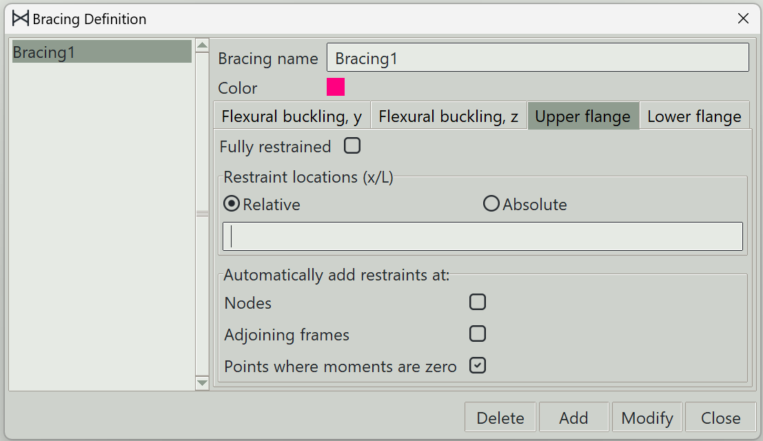
- Upper flange: Tab for entering restraints against lateral torsional buckling for the upper flange.
- Lower flange: Tab for entering restraints against lateral torsional buckling for the lower flange.
Obviously, the last two only make sense for certain steel sections. But those are often encountered, so it makes sense to give them this much attention.
4. Fully restrained
When this button is checked, the frame is fully restrained against the concerned type of buckling.
5. Restraint locations
Values can be entered in this entry box to indicate the specific locations where restraints are present for the selected type of buckling. The locations can be provided relatively or absolutely.
6. Nodes
When this is checked, restraints will be assumed at all points where nodes are present along the frame.
7. Adjoining frames in the buckling plane
As the name suggests, the frame will be assumed to be braced by frames lying in its buckling plane and connected to the frame in question. This is only available for flexural buckling.
8. Adjoining frames
This is only available for lateral torsional buckling. When checked, everywhere a flange is connected to another frame will be assumed as a position of restraint.
9. Points where moments are zero
Some codes allow the consideration of points of zero bending moments about the y-axis as a position of restraint against lateral torsional buckling. This is what this is for.
10. Delete button
Deletes the selected bracing properties.
11. Add button
Adds a new bracing property.
12. Modify button
Updates an existing bracing property.
13. Close button
Closes the window.