Frame Point Load Definition
This tab is used to define point loads that can be assigned to frames. The left pane displays a list of frame point loads available in the model, while the right pane shows the parameters of the selected load. The same area is also used to input parameters when creating a new frame point load.
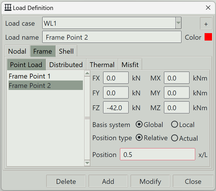
1. Load case
Select the load case under which this load is defined.
2. + button
Opens the load case definition window so that you can add a new load case.
3. Load name
A unique name for the load. It can be left blank, in which case the program will generate one automatically.
4. Color
The color assigned to this load for visualization purposes.
5. Load components
A set of entry fields is provided where you can define the components of the load vector. At least one component must be non-zero for the definition to be valid. Any empty field is treated as zero.
- FX: Force component in the global or local x-axis.
- FY: Force component in the global or local y-axis.
- FZ: Force component in the global or local z-axis.
- MX: Moment component about the global or local x-axis.
- MY: Moment component about the global or local y-axis.
- MZ: Moment component about the global or local z-axis.
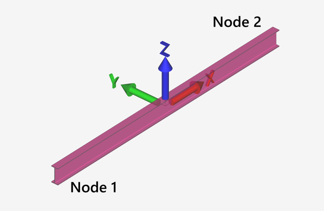
6. Basis system
You can define the load in either the global coordinate system or the frame’s local coordinate system. The frame local coordinate system is illustrated below:
7. Position type
Specifies how the position of the load along the frame is defined. It can be specified either in absolute terms or as a relative value between 0 and 1.
8. Position
The location where the load is applied along the length of the frame. If defined as a relative value, it must be between 0 and 1. If defined as an absolute value, it must be between 0 and the total length of the frame.
9. Delete button
Removes the selected load from the model.
10. Add button
Creates a new load using the specified parameters.
11. Modify button
Updates the parameters of the selected load.
12. Close button
Closes the window.