Shells: Maps
This tab is used to visualise internal forces on shells as maps. The sign convention is the usual right hand system as shown.
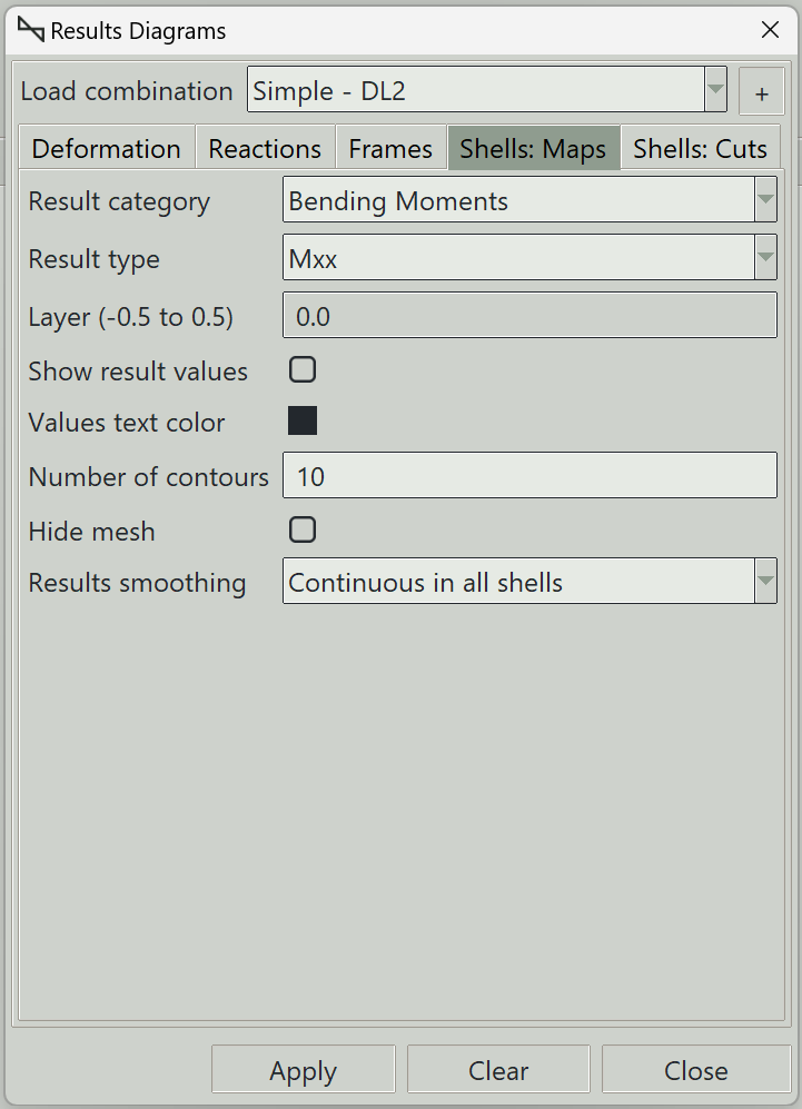
1. Load combination
The name of the load combination to display results for.
2. Result category and type
Various categories of shell results can be visualised. The Results category field is used to select the category, while the Results type is used to select the type of result under each category. The various categories and their types are described below.
3. Membrane forces
The sign convention for membrane forces is shown below:
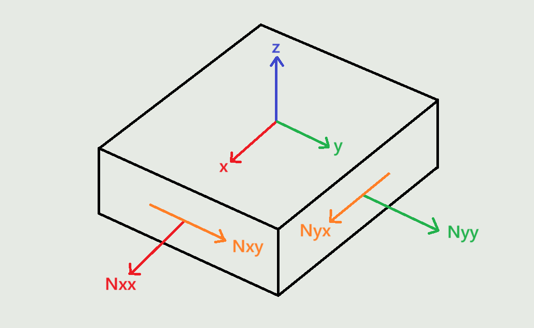
The membrane forces are as follows:
- Nxx: Membrane force per unit length in the local x-direction on a face perpendicular to the local x-axis. It causes normal stress in the local x-axis direction.
- Nyy: Membrane force per unit length in the local y-direction on a face perpendicular to the local y-axis. It causes normal stress in the local y-axis direction.
- Nxy: Membrane force per unit length in the local y-direction on a face perpendicular to the local x-axis. It causes shear stress in the local x-axis direction. Nxy and Nyx are equivalent in magnitude.
4. Shear forces
The sign convention for shear forces is shown below:
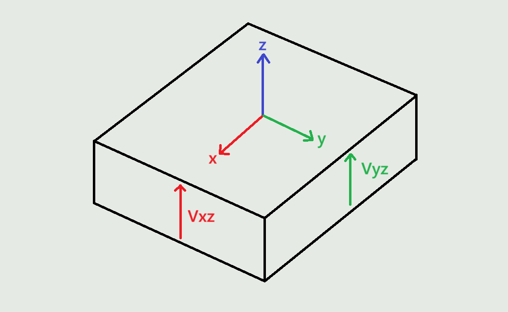
The shear forces are as follows:
- Vxz: Shear force per unit length in the local z-direction on a face perpendicular to the local x-axis.
- Vyz: Shear force per unit length in the local z-direction on a face perpendicular to the local y-axis.
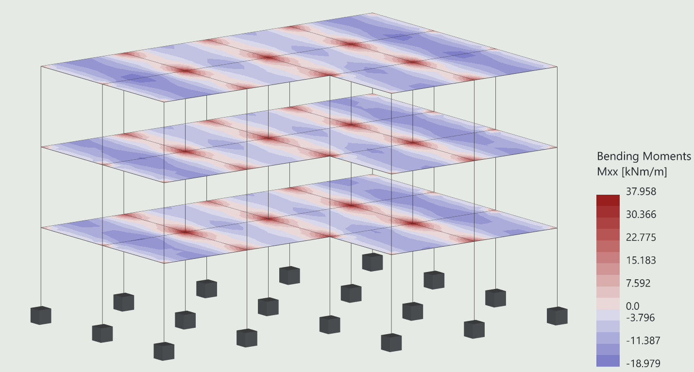
5. Bending moments
The sign convention for bending moments is shown below:
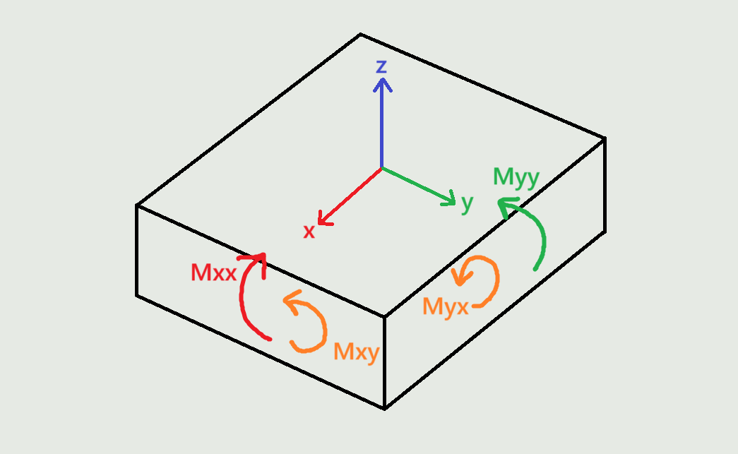
The bending moments are as follows:
- Mxx: Bending moment per unit length about the local y-axis on a face perpendicular to the local x-axis. It causes normal stress in the local x-axis direction.
- Myy: Bending moment per unit length about the local x-axis on a face perpendicular to the local y-axis. It causes stress in the local y-axis direction.
- Mxy: Bending moment per unit length about the local x-axis on a face perpendicular to the local x-axis. Mxy and Myx are equivalent in magnitude.
6. Design bending moments
Design bending moments calculated using the Wood-Armer method. These are the moments you are supposed to use when performing reinforced concrete design.
- Mx+: Design bending moment per unit length about the local y-axis. Controls the top reinforcement parallel to the local x-axis.
- My+: Design bending moment per unit length about the local x-axis. Controls the top reinforcement parallel to the local y-axis.
- Mx-: Design bending moment per unit length about the local y-axis. Controls the bottom reinforcement parallel to the local x-axis.
- My-: Design bending moment per unit length about the local x-axis. Controls the bottom reinforcement parallel to the local y-axis.
Reference:
Wood, R. H., et al. "The Theory of the Strip Method for Design of Slabs.(Includes Appendix)." Proceedings of the Institution of Civil Engineers 41.2 (1968): 285-311.
7. Membrane stresses
The membrane stress or angle of principal membrane stress. The sign convention is as described above for Membrane forces.
- Sxx: Membrane stress in the local x-direction on a face perpendicular to the local x-axis.
- Syy: Membrane stress in the local y-direction on a face perpendicular to the local y-axis.
- Sxy: Membrane stress in the local y-direction on a face perpendicular to the local x-axis. Sxy and Syx are equivalent in magnitude.
- Major: Major principal membrane stress.
- Minor: Minor principal membrane stress.
- Angle: Angle of principal membrane stress.
8. Shear stresses
The shear stress in the shell. The sign convention is as described above for Shear forces.
- Sxz: Shear stress in the local z-direction on a face perpendicular to the local x-axis.
- Syz: Shear stress in the local z-direction on a face perpendicular to the local y-axis.
9. Bending stresses
The bending stress or angle of principal bending stress (in degrees). The sign convention is as described above for Bending moments.
- Sxx: Bending stress in the local x-direction on a face perpendicular to the local x-axis.
- Syy: Bending stress in the local y-direction on a face perpendicular to the local y-axis.
- Sxy: Bending stress in the local y-direction on a face perpendicular to the local x-axis. Sxy and Syx are equivalent in magnitude.
- Major: Major principal bending stress.
- Minor: Minor principal bending stress.
- Angle: Angle of principal bending stress.
10. Total stresses
The total stress or angle of principal total stress (in degrees). The sign convention is as described above for Membrane forces and Bending moments.
- Sxx: Total stress in the local x-direction on a face perpendicular to the local x-axis.
- Syy: Total stress in the local y-direction on a face perpendicular to the local y-axis.
- Sxy: Total stress in the local y-direction on a face perpendicular to the local x-axis. Sxy and Syx are equivalent in magnitude.
- Major: Major principal total stress.
- Minor: Minor principal total stress.
- Angle: Angle of principal total stress.
- Von Mises: Two-dimensional Von Mises equivalent stress for plane stress conditions.
11. Layer (-0.5 to 0.5)
The layer at which the stress is required, ranging from -0.5 (bottom surface) to 0.5 (top surface)
12. Show result values
Whether to display results values on the maps.
13. Values text color
The text color of the results values.
14. Number of contours
The number of divisions to use in the color map.
15. Hide mesh
Whether to hide the mesh when the result maps are drawn.
16. Results smoothing
Due to numerical approximation, results from one finite element may not exactly match those from an adjacent element. Some averaging may therefore be required to produce smoother and more representative results. You can choose from the following smoothing options:
- None: No smoothing is performed. Raw element results are displayed.
- Continuous in each shell: Result values along shared edges are averaged between adjacent finite elements belonging to the same shell.
- Continuous in model: Result values along shared edges are averaged between adjacent finite elements throughout the model, even when they belong to different shells, provided they are connected. Use this option with care. Different shells may have different local axis orientations, meaning the results may not represent the same physical directions and may therefore not be suitable for averaging.
17. +/- button
You can add or remove points on the shell where result values can be shown. This button launches the window that you use to define these points.
Result values for a point are only displayed if the point lies on a shell.
18. Add Results Label Points Window
Pick points on shells where you want to draw show result values. You can also enter the coordinates manually and click the Accept button.
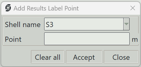
18.1 Shell name
The name of the shell on which the point is to be created.
18.2 Point
The x, y, z coordinates of the point.
18.3 Clear all button
Deletes all result label points.
18.4 Accept button
Adds a point with the entered coordinates.
18.5 Close button
Closes the result label point definition window.
19. Apply button
Plots the selected results type. If some elements are selected, results are displayed only for those elements.
20. Clear button
Clears all result graphics from the model view.
21. Close button
Closes the window and clears all result graphics.